|
The G 600 Pr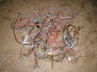 ep and Much More ep and Much More
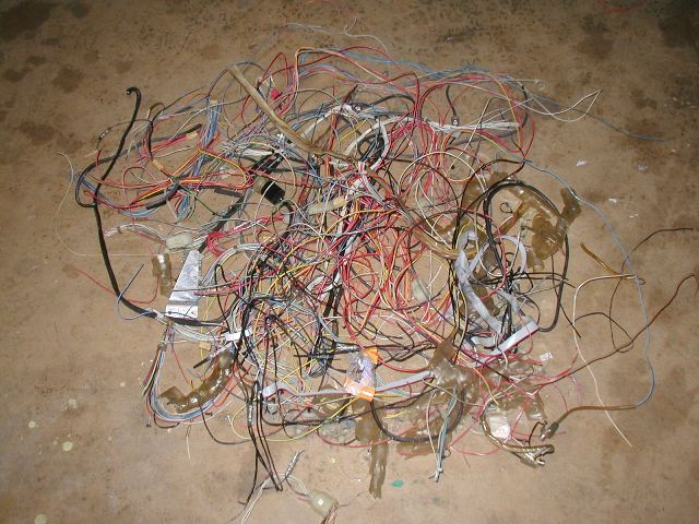
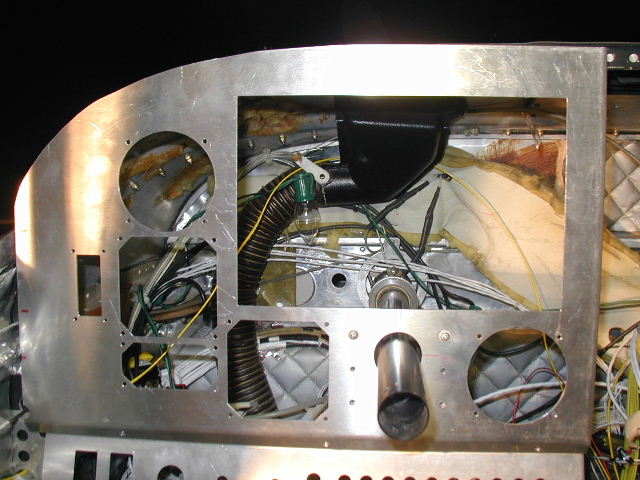
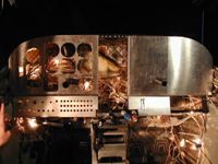
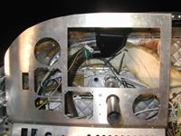
With the panels and instruments removed its time to start
cutting out the old wiring. Sometimes these piles can weigh
as much as 50 pounds! In an older Cessna its pretty easy to
tell which wires are to be removed and which ones stay. Basically all wiring that was installed for the basic aircraft electrical system such as Nav lights, Pitot Heat, instruments, etc are white with wiring numbers stamped onto each individual wire. On the other hand all Avionics associated wires are color coded. Since this is a complete instrument panel and radio stack make-over
everything is removed including all of the circuit breakers, switches, lights etc. In this particular installation, since a JPI EDM 930 will be installed, all instrumentation wiring and interfaces including the instrument cluster will be removed as well.
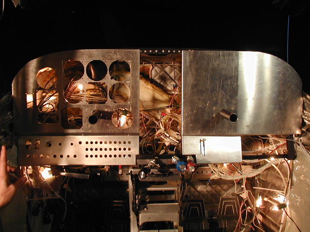
The New Panel Fabrication Starts to take Shape
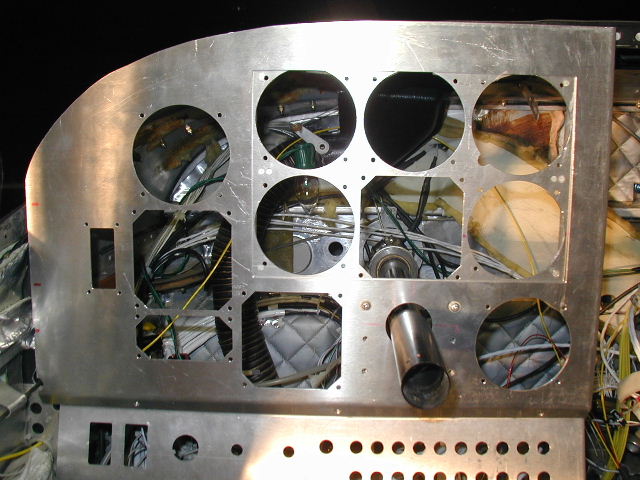
As stated before this panel must be able to be retrofitted with a Garmin G600 when it comes available without fabricating a new pilots side panel. The only way to achieve this is to create an inset panel that will mount all of the instruments that will be replaced by the G600 in the same mounting area. This panel, along with the 6 flight instruments, when removed, leaves an opening exactly the size needed to insert the G600 mounting tray.
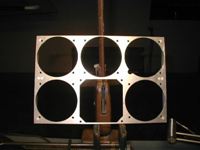 The inset panel will mount in the same fashion as all radio racks with mounting screws fastening into side-rails. In the panel will go the new NSD 1000 and the New electric artificial horizon which comes with the Century Triden Plus system. These two instruments will move over to the mounting holes to the left of the inset panel when the G600 is installed and will serve as the back-ups. These two mounting holes will be blanks until this time comes. It took a lot of squeezing to get all 6 of the instruments to fit into this panel, but they do! and with UMA light wedges to boot. The inset panel will mount in the same fashion as all radio racks with mounting screws fastening into side-rails. In the panel will go the new NSD 1000 and the New electric artificial horizon which comes with the Century Triden Plus system. These two instruments will move over to the mounting holes to the left of the inset panel when the G600 is installed and will serve as the back-ups. These two mounting holes will be blanks until this time comes. It took a lot of squeezing to get all 6 of the instruments to fit into this panel, but they do! and with UMA light wedges to boot.
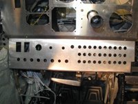 We had originally planned to locate the Avionics Circuit Breaker panel on the copilots side just above the glovebox door but Phil nixed that plan in favor of placing them all in the pilots switch panel so he could manage them better if needed. Since now we must accommodate all of the new equipment with individual circuit protection and that we are also installing all the circuit breakers necessary for the installation of the G600 (Display, AHRS, magnetometer, and airdata computer), it was necessary to arrange the breakers into three rows. A pretty full switch panel to say the least. This makes it a challenge for the screen printer to arrange all of the text needed on the panel without placing it too close to the switch and breaker mounting hardware We had originally planned to locate the Avionics Circuit Breaker panel on the copilots side just above the glovebox door but Phil nixed that plan in favor of placing them all in the pilots switch panel so he could manage them better if needed. Since now we must accommodate all of the new equipment with individual circuit protection and that we are also installing all the circuit breakers necessary for the installation of the G600 (Display, AHRS, magnetometer, and airdata computer), it was necessary to arrange the breakers into three rows. A pretty full switch panel to say the least. This makes it a challenge for the screen printer to arrange all of the text needed on the panel without placing it too close to the switch and breaker mounting hardware
Some of our Panel Details (double click for a larger picture)
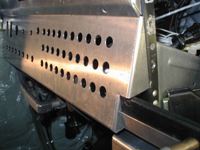 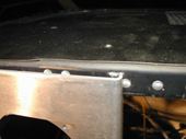 
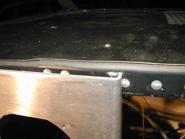
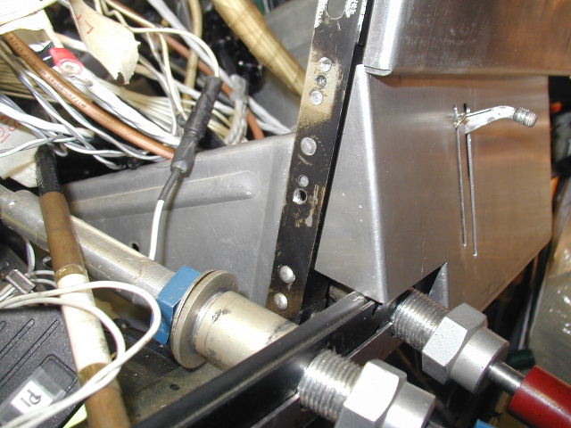
We pay a lot of attention to detail when it comes to proper bends and how individual panel sections fit with respect to each other and to the mounting surfaces. All of our custom instrument and lower panels are made to be installed in the same plane as the original plastic overlays were. although they don't protrude out from the mounting structure as far as the face of the radio do, they are not just flat panels bolted to the structure. Our panels are mounted with standoffs. (double click the center picture above to see an example of the edge bend at the radio stack).
Web site and all contents © Copyright Avionicswest.net, All rights reserved.
|